
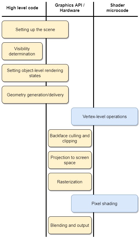
The diagram below gives a rough overview of the graphics pipeline and shows the division of work between our code and the graphics API, which is WebGL in our case. The blue nodes are the shaders, these are microprograms we need to write that are executed on the GPU for every vertex and pixel that needs to be processed. Shader programs for WebGL are written in the OpenGL Shading Language (GLSL).
It’s important to keep in mind that there is no such thing as a typical real-time rendering pipeline. Different applications require different strategies and the one that we present here is just one of many ways to implement a graphics pipeline. You should also be aware that our description is of the conceptual flow of data through the pipeline. The steps we present here are often performed in parallel or out of order for performance reasons, as you’ll see in our example.
Now for the practical part, our application is split up into two functions, an
init() function and a render() function. The init function is called when the page
has finished loading and the render function is called at the end of the
init function. From here on the render function will keep calling itself by calling
requestAnimationFrame(), with itself as argument.
This way a callback is executed to the render function only when a new frame is
needed and not when the browser window is not active.
window.onload = function init()
{
    // setting up the scene, configuring camera, ...

    render();
}

function render()
{
    // apply rotation, draw primitives, ....

    requestAnimFrame( render );
}
As for the division of work between the two functions, it’s very
straightforward. The init function takes care of the tasks that need to executed
only once, such as setting up the scene, compiling the shaders, etc. While the
render function takes care of the tasks that need to be performed every
rendering cycle. And it’s here that the practical part will sometimes deviate
from the conceptual presentation. Often times it makes more sense to perform
certain tasks once instead of repeating them every rendering cycle.
Setting up the scene
First we need to set up the scene. This involves loading our models and setting up the camera, we need to choose a point of view from where we want to render the scene. We also need to prepare the buffers that we’ll use in our vertex and fragment shaders.
Normally this is also where we set up our lighting model but, as you might have noticed, our 3D cube looks a bit flat. That’s because we’ve left out the interaction between light and surfaces in our example to keep things simple. The lightning strategy we’re applying here is called the “flashlight in the eye” model and corresponds to a single light source at the center of projection, which means there are no visible shadows because any shadows are behind visible objects.
We start our application by declaring a couple of global variables and by
setting up our WebGL context. For creating the WebGL context we use the
setupWebGL() function from the WebGLUtils module provided by Google. This
function creates a WebGL context and shows a relevant error message when
creation failes.
var gl;

window.onload = function init()
{
    var canvas = document.getElementById("gl-canvas");

    gl = WebGLUtils.setupWebGL(canvas);
    if (!gl) {
        alert("WebGL isn’t available");
    }

    ...

    render();
}
Next we create and configure the cube. We won’t go into detail on how our cube
object and the createCube() function work, you can always download the source
files of this project and take a look yourself. It suffices to know that this
function will create a cube of a given size that is centered at the origin. We
also configure the color of the faces and the edges with an RGBA value. Normally
we would also need to position our cube in the scene but because the
cube is the only object that we are rendering we can conveniently leave it
centered at the origin.
The theta variable will keep track of the rotation of the cube, we initialize it to the zero vector.
...

var cube, theta;

window.onload = function init()
{
    ...

    cube = createCube(1.0);
    cube.colorFaces = vec4(0.0, 1.0, 0.0, 0.3);
    cube.colorEdges = vec4(0.0, 0.0, 0.0, 1.0);
    theta  = [0.0, 0.0, 0.0];

    ...

    render();
}
The viewport() function of the WebGL context specifies the transformation from
normalized device coordinates to window coordinates. The mapping to 2D window
coordinates happens during the projection to screen space, one of the later
stages of the pipeline. This is carried out by the graphics API, all we need to
do is specify the width and height of our viewport and the coordinates of the
lower left corner. We leave the lower left corner coordinates to (0,0) and pass the
width and height of the HTML canvas element to the viewport function.
The clearColor() function specifies the value that is used when clearing color
buffers. This controls the color of the background of our viewport and we set
this to white. We also enable blending because we want to make the faces of the
cube transparent, showing the edges on the backside of the cube. This means
we have to disable the depth test, as this will prevent the alpha blending
of pixels in the final step of the pipeline.
Next we compile and link our vertex and fragment shader and attach them to our
WebGL context. We write our shaders in the HTML page that loads the javascript
program, thus we pass the HTML id attributes of our shader programs to the
initShaders() function. The initShaders function takes care of the
compilation and linking of the shaders for us. We won’t dive further in the code
of this function but once again you’re free to download this project and take a
look yourself.
...

window.onload = function init()
{
    ...

    gl.viewport(0, 0, canvas.width, canvas.height);
    gl.clearColor(1.0, 1.0, 1.0, 1.0);

    gl.enable(gl.BLEND);
    gl.disable(gl.DEPTH_TEST);

    program = initShaders(gl, "vertex-shader", "fragment-shader");
    gl.useProgram(program);

    ...

    render();
}
Next up we define the camera using three vectors, one for the position of the camera (eye), one to specify where the camera is pointing at (at) and the final vector specifies the up direction of the camera (up). Because we’re using a static camera we can also create our view transform matrix in this step. We use the three camera vectors to construct a transformation matrix in the lookAt() function. This transformation matrix takes the vertice positions from world space coordinates to camera space, also referred to as view or eye space.
By default WebGL uses a right handed coordinate system for world space with the z-axis pointing south. Although we are free to use whichever coordinate system for our view space, we will use the same convention for the view space and transform our vertices to a right handed coordinate system with the z-axis pointing out of the screen towards the viewer.
Now we need to pass the view matrix to our shader program. First we use the
getUniformLocation() function to get an interface to the uniform variable in our
vertex shader. Using this interface we can pass the value of our view matrix to the shader using uniformMatrix4fv().
...

const eye = vec3(0.0, 0.0, 2.0);
const at = vec3(0.0, 0.0, 0.0);
const up = vec3(0.0, 1.0, 0.0);

window.onload = function init()
{
    ...

    var modelViewMatrix = lookAt(eye, at, up);
    modelViewMatrixLoc = gl.getUniformLocation(program, "modelViewMatrix");
    gl.uniformMatrix4fv(modelViewMatrixLoc, false, flatten(modelViewMatrix));

    ...

    render();
}
We also need to define the projection matrix. The projection matrix transforms the vertices from camera space to clip space, also known as the canonical view volume space. The projection matrix is also referred to as the clip matrix. It serves two primary functions. It prepares the vertices for projection by putting the proper value in w, the fourth element of homogeneous vertex coordinates, so that the homogeneous division carried out during the projection to screen space produces the desired projection. It also applies zoom and prepares the vertices for clipping by scaling the x, y and z values so they can be compared to w. Clipping is the process that ensures that the vertices we’re about to render are completely inside the view frustum.
Both clipping and projection are carried out by the rendering API which is WebGL in our case. The job of the projection matrix is to prepare our vertices for these operations.
The perspective() function creates a perspective projection matrix. We need to
pass a field of view value, an aspect ratio and the near and far clip plane
values. We define the aspect ratio by dividing the HTML canvas width by its
height. The field of view value is inversely related to the zoom value, it’s
also a more convenient metric for humans to use. Together with the distance of
the near and far clip plane it specifies the shape of the view frustum against
which clipping occurs.
We pass the projection matrix to the vertex shader in similar fashion as we did for the view matrix.
...

const fov = 55;
const near = 0.3;
const far = 5;

window.onload = function init()
{
    ...

    var aspectRatio = gl.canvas.width / gl.canvas.height;
    var projectionMatrix = perspective(fov, aspectRatio, near, far);
    projectionMatrixLoc = gl.getUniformLocation( program, "projectionMatrix" );
    gl.uniformMatrix4fv(projectionMatrixLoc, false, flatten(projectionMatrix));

    ...

    render();
}
The final task that falls under setting up the scene is clearing the color buffer. This needs to be done every rendering cycle and it’s the first line we execute in the render function.
...

function render()
{
    gl.clear( gl.COLOR_BUFFER_BIT );

    ...

    requestAnimFrame( render );
}
Visibility determination
After setting up the scene we need to determine which objects are visible. This is a form of high level culling and is very important for the performance of complex applications. For smaller applications and demo’s this step is usually skipped. Because we are only rendering one object that stays at the center of our view we too can safely skip this step.
Setting object-level-rendering states
In this step the properties of the individual objects are configured that are important for rendering. Most notably the material properties of the object that specify the diffuse color. In our example we set the color of the cube using an RGBA value but often times a texture map is used instead.
Aside from the color we also configure the rotation of the cube. We do this by increasing the theta values every rendering cycle, subtracting 360 degrees when they made a full rotation. As with the projection and view matrix, we pass these values to the vertex shader.
For the color we pass the colors we configured for the cube in two subsequent steps, because we will be rendering the faces as well as the edges of the cube. First we pass the color of the faces for drawing the faces and after that we pass the color of the edges for drawing the edges.
We create the interfaces to the uniform variables for color and rotation once,
inside the init function.
...

window.onload = function init()
{
    ...

    colorLoc = gl.getUniformLocation(program, "fColor");
    thetaLoc = gl.getUniformLocation(program, "theta");

    ...

    render();
}

function render()
{
    gl.clear( gl.COLOR_BUFFER_BIT );

    theta[0] += 0.5;
    theta[1] += 1.0;

    if (theta[1] > 360.0) {
      theta[1] -= 360.0;
    }
    if (theta[0] > 360.0) {
      theta[0] -= 360.0;
    }

    gl.uniform3fv(thetaLoc, flatten(theta));

    gl.uniform4fv(colorLoc, flatten(cube.colorFaces));

    // draw faces

    gl.uniform4fv(colorLoc, flatten(cube.colorEdges));

    // draw edges

    requestAnimFrame( render );
}
Geometry generation/delivery
In this step we deliver our geometry to the rendering API. WebGL provides multiple options for drawing primitives, such as triangles, triangle fans, triangle strips, line segments, … For our rotating cube we want to draw the faces and the edges using a different color. We’ll be delivering the faces as triangles and the edges as line segments.
We won’t be transforming the vertices of the cube in our application program.
We will pass the rotation values of the cube to the vertex shader and perform the
rotation there. This means we only need to deliver the geometry once to the
rendering API so we can do this inside the init function.
First we create an array which will hold the geometry we want to render. We add the
faces of the cube as triangles (polygons) and also add the edges as line segments.
Now we need to set up our buffer and fill it with our data. First we create the
buffer using createBuffer(), we set it as the active buffer we want to work on
using the bindBuffer() function, which binds our buffer to the ARRAY_BUFFER bind
point, a global variable internal to WebGL. Finally the bufferData() function
allows us to fill the buffer with our data.
Now we have filled our buffer with data but we still need attach it to our
vertex shader. To do this we need to create an interface to the position
attribute in the vertex shader using the getAttribLocation()
function, similar to how we created the interfaces to the uniform variables. Using the
vertexAttribPointer() function we specify the memory layout of the buffer
currently bound to the ARRAY_BUFFER bind point. In our example we specify that
our vertex attributes each hold four floating point numbers. Finally we
turn on the vertex attribute using enableVertexAttribArray().
...

window.onload = function init()
{
    ...

    var points = [];
    points = points.concat(cube.faces_as_triangles());
    points = points.concat(cube.edges_as_line_segments());

    var vBuffer = gl.createBuffer();
    gl.bindBuffer(gl.ARRAY_BUFFER, vBuffer);
    gl.bufferData(gl.ARRAY_BUFFER, flatten(points), gl.STATIC_DRAW);

    var vPosition = gl.getAttribLocation(program, "vPosition");
    gl.vertexAttribPointer(vPosition, 4, gl.FLOAT, false, 0, 0);
    gl.enableVertexAttribArray(vPosition);

    render();
}
Aside from delivering the geometry to the rendering API we can also generate geometry inside a geometry shader, something we won’t be discussing in this article.
Vertex-level operations
Once everything is setup and the geometry is delivered to the rendering API we can start with the operations at vertex level. These operations are performed by a user-supplied microprogram called the vertex shader. The most important operations carried out by the vertex shader are the transformation of vertices from world space to camera space and preparing the vertices for clipping and projection. Other vertex level operations might include skinning for animation, texture coordinate generation and vertex lighting.
We execute the shaders on the GPU by calling drawArrays(), specifying what
kind of primitives we want to draw, the starting index and the number of indices
we want to draw. We do this every rendering cycle two times,
once for the faces and once for the edges, after passing the correct color to
the shader as we discussed when setting the object-level-rendering states.
...

function render()
{
    ...

    gl.uniform4fv(colorLoc, flatten(cube.colorFaces));
    gl.drawArrays( gl.TRIANGLES, 0, cube.count_vertices_faces );

    gl.uniform4fv(colorLoc, flatten(cube.colorEdges));
    gl.drawArrays( gl.LINES, cube.count_vertices_faces,
      cube.count_vertices_edges );

    requestAnimFrame( render );
}
The vertex shader is run once for every vertex we pass to the API and we also have access to the data we passed to the shader in the previous steps. We specify our shaders in the HTML page that loads our javascript application. It’s also possible to specify the shaders in a separate file, although you might encounter some problems with the security settings of your browser. For WebGL the shaders are written in the OpenGL Shading Language (GLSL).
Now on to our shader. The first thing we do is convert the rotation angles
from degrees to radians, as this is the unit assumed by GLSL. Next we compute
the cosine and sine values of the rotation angles. Now we have
all the information we need to construct our rotation matrices to rotate the
vertices of the cube. The rx matrix defines a rotation around the x-axis and the
ry matrix defines a rotation around the y-axis. We can apply our rotation
matrices, the model-view matrix and the projection matrix to the vertex
coordinates by multiplying the matrices with the vector coordinates.
It’s important to keep in mind that the order of multiplication matters. WebGL and OpenGL use column vectors by default, this means we need to read matrix vector multiplication from right to left. So in our example the rotation around the y-axis is applied first, then the rotation around x-axis, next the model-view transformation and finally the projection transformation.
<script id="vertex-shader" type="x-shader/x-vertex">
  attribute vec4 vPosition;
  uniform mat4 modelViewMatrix;
  uniform mat4 projectionMatrix;
  uniform vec3 theta;

  void main()
  {
    vec3 angles = radians(theta);
    vec3 c = cos(angles);
    vec3 s = sin(angles);
    mat4 rx = mat4(
      1.0, 0.0, 0.0, 0.0,
      0.0, c.x, s.x, 0.0,
      0.0, -s.x, c.x, 0.0,
      0.0, 0.0, 0.0, 1.0
    );
    mat4 ry = mat4(
      c.y, 0.0, -s.y, 0.0,
      0.0, 1.0, 0.0, 0.0,
      s.y, 0.0, c.y, 0.0,
      0.0, 0.0, 0.0, 1.0
    );

    gl_Position =
        projectionMatrix * modelViewMatrix * rx * ry * vPosition;
  }
</script>
Clipping, backface culling, projection and rasterization
The next three steps are performed by the rendering API so we won’t have to perform these ourselves. We prepared our vertices for two of them in the vertex shader: clipping and projection. We’ll give a short overview of what these three steps do exactly.
Clipping happens after the vertices have been transformed into clip space. In this test the primitives we want to render are clipped against the view frustum. In our example the primitive are lines and triangles. Primitives that are completely outside the view frustum are rejected as being invisible, primitives that have one more vertices inside and one or more outside are clipped so that all the vertices are inside the frustum. Primitives that are completely inside the frustum are left as they were.
The next test is backface culling, it’s a form of hidden surface removal where triangles are removed that are not facing the camera. Most API’s, WebGL including, allow the programmer to turn this option on or off.
Next our 3D vertices are projected and mapped to the 2D screen-space coordinates of the output window. These coordinates are continuous floating point values, yet we need to render pixels which are discrete. This is were rasterization comes into play. Rasterization is the process of selecting which pixel should be drawn for a particular primitive. The values that were computed at vertex level, such as colors, are interpolated across the face for each pixel. These values are then passed on to the pixel shader.
During rasterization the depth value for each pixel is also interpolated for each pixel and stored in the depth buffer. Often the clip space z-coordinate is used as depth value, that’s why the depth buffer is also referred to as the z-buffer. The depth value is used to determine if an object is occluded by an object closer to the camera, in which case the pixel is discarded. This test can be done before or after the pixel shader, as the depth value can be modified in the pixel shader. For our example we disabled the depth test so it wouldn’t interfere with our transparent faces.
Pixel Shading
Pixel shading is the name for the process of computing a color for each pixel. This step is performed by a user-supplied microprogram called the pixel shader, also referred to as the fragment shader. This shader is run once for every pixel. The pixel shader takes the values from the vertex shader, which are interpolated across the face during rasterization, and outputs a color and alpha value for each pixel.
Similar to the vertex shader we specify the pixel shader in the HTML page that loads our javascript application, although it’s also possible to specify the shaders in a separate file. Normally the pixel shader would be where we apply lighting, yet it’s also possible to do this in the vertex shader. Because we’re not doing any lighting calculations our pixel shader is very short, we simply output the color value that was passed during rasterization. The first line of the shader sets the precision that the GPU uses when working with floating point values to medium, this ensures that our shader will run on all implementations that support WebGL.
<script id="fragment-shader" type="x-shader/x-fragment">
  precision mediump float;
  uniform vec4 fColor;

  void main()
  {
    gl_FragColor = fColor;
  }
</script>
Blending and output
At the end of the pipeline we have a color, opacity and depth value for each pixel. If the depth test is enabled and wasn’t executed before the fragment shader than it’s executed here. Next up is the alpha test: a threshold is used to test the opacity of the pixel, if the alpha value of the pixel is not higher than this predefined value than the pixel is rejected.
Finally the frame buffer is updated with the color value for the pixels that passed the depth and alpha test. If blending is not enabled than the current value in the frame buffer is replaced by the pixel color value. Otherwise the new value is combined with the existing one proportional to the alpha values, a process known as alpha blending.
This concludes our overview of the rendering pipeline. Use the download button below to download our rotating cube example if you want to take a more in depth look at the code. And once again, if you have questions or remarks feel free to drop a comment below!